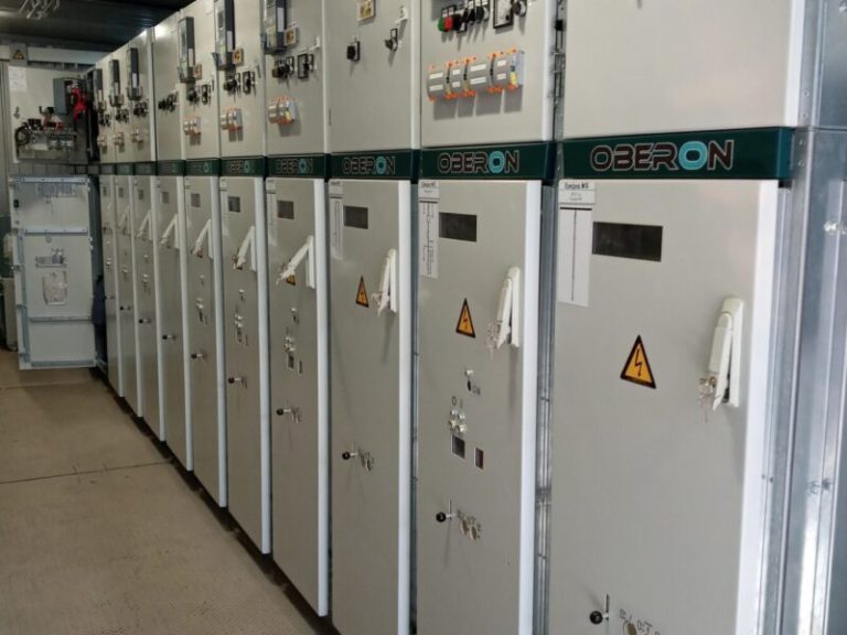
The Medium Voltage Switchgear OBERON is designed for the reception and distribution of alternating current (AC) power with a frequency of 50/60 Hz. OBERON switchgear panels are equipped with high-quality switching, measuring, and microprocessor-based protection devices from leading global manufacturers. The OBERON modular switchgear units are manufactured at the production facilities of S-Engineering in accordance with TU U 27.1-34944005-002:2020 and EN 62271-200 standards.
More About the Technology
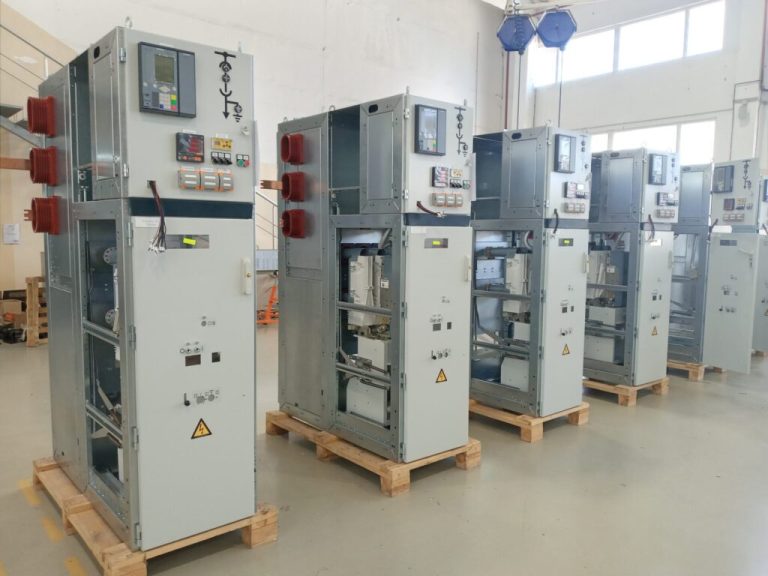
Complete switchgear with withdrawable truck
OBERON withdrawable switchgear is a medium-voltage power distribution system for substations, industrial facilities, and power networks, designed for safe control and protection of electrical circuits. The withdrawable truck design ensures easy maintenance, quick equipment replacement, and a high level of operational safety.
Cassette-type complete switchgear
Constraction
Constraction of Oberon cells:
Service life until major overhaul is up to 25 years.
Minimum dimensions of feeder cells – 600 mm width.
Enclosure made of sheet steel EN 10346-DX51D+Z275.
Steel thickness 2–2.5 mm with zinc coating (275 g/m²). External doors are powder coated with optional RAL color selection.
Anti-corrosion coating with multi-stage surface preparation.
Each compartment has an overpressure relief channel.
Scope of supply with accessory kits; minimum two sets:
Transfer lever rod for mechanical circuit breaker switching ON/OFF.
Double-bit key for the switching apparatus compartment door.
Double-bit key for the low-voltage (LV) compartment door.
Operating handle for the feeder or busbar earthing switch.
Cranking handle for charging the circuit breaker closing spring.
Degree of protection of enclosure ip4x:
Protection against solid foreign objects, diameter 1 mm.
Protection against electric shock.
Switching apparatus compartment
Equipped with SEV-12 circuit breakers from “S-Engineering” and 3AE from “Siemens”.
All switching operations are only possible when the high-voltage compartment door is closed.
Overpressure relief is directed upwards.
Front doors and side locking walls of the switchgear cells have powder coating.
Separate operating mechanisms for the protective shutters – for the busbar compartment and the connection compartment.
The high-voltage compartment door is resistant to overpressure impacts.
Side metal cable ducts for routing control cables.
Access to the compartment is only possible depending on the current interlocking status (high-voltage compartment door interlocking is set depending on the position of the switching apparatus truck).
Option: test sockets for the capacitive voltage presence indicating system.
Interlocking
Interlocking conditions provided by EN 62271-200 are fulfilled.
Earthing switch operation is only possible when the circuit breaker truck is in the isolated/test position.
Movement of the circuit breaker truck is only possible when the circuit breaker is OFF (in the “OFF” position) and the earthing switch is open (OFF).
High-voltage compartment door interlocking is logically dependent on the position of the circuit breaker truck.
The high-voltage compartment door can only be opened if the circuit breaker truck is in the isolated/test position.
Option: electromagnetic interlocks.
Motorized racking-in/racking-out of the circuit breaker and motorized control of the earthing switch are possible.
Busbar & cable component
Overpressure relief is directed upwards through a specialized pressure relief duct.
Option: transverse partitioning of the busbar compartment with separate partitions from cell to cell.
Busbars are made of electrolytic copper; busbars of adjacent cells are connected to each other using busbar links.
Option: insulated busbars.
Access via rear and roof panels of the compartment secured by threaded fasteners, requiring the use of a special tool only.
Coupling electrode for the capacitive voltage presence indicating system.
Options: possibility of integrating the following components: voltage transformer, busbar earthing switch, current transformer.
Designed for connecting single-core cables with a maximum cross-section of up to 6×500 mm2 per phase, and three-core cables with a maximum cross-section of up to 3х300 mm2 per cell.
Independently opening protective shutters provide access for cable inspection.
Earthing busbar.
Connection (cable entry) from the front or rear.
Option: overpressure impact-resistant floor panel
Usage of block-type current transformers.
Access via rear panels which requires the use of a special tool only.
Access to the primary contacts of the current transformer is possible from the front side.
Electrode for the capacitive voltage presence indicating system.